Replaces
Part Details
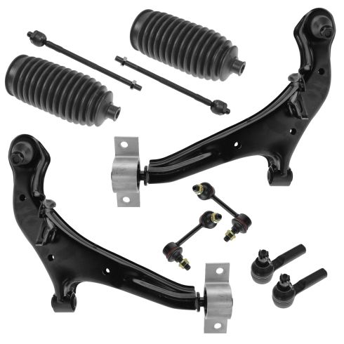
Install Tip: When replacing steering components, have a professional alignment performed afterwards. This ensures proper tracking and even tire wear.
Complete Repair in One Purchase - Stop searching for parts individually and complete your repair with a customized kit or set from DIY Solutions.
High-Quality Parts from Trusted Brands - DIY Solutions' kits and sets are selected from the best automotive brands and include hard-to-find and even obsolete parts you may need for your vehicle.
Guaranteed Fit - DIY Solutions ensures its selected parts are quality-tested to guarantee fit and function.
Item Condition:
New
Attention California Customers:
 WARNING: This product can expose you to chemicals including Lead and Lead Compounds, which are known to the State of California to cause cancer, and birth defects or other reproductive harm. For more information, go to www.P65Warnings.ca.gov.
Lifetime Warranty
This item is backed by our limited lifetime warranty. In the event that this item should fail due to manufacturing defects during intended use, we will replace the part free of charge. This warranty covers the cost of the part only.
FREE Shipping is standard on orders shipped to the lower 48 States (Contiguous United States). Standard shipping charges apply to Hawaii and Alaska.
Shipping is not available to a P.O. Box, APO/FPO/DPO addresses, US Territories, or Canada for this item.
Expedited is available on checkout to the United States, excluding Alaska, Hawaii.
Final shipping costs are available at checkout.


Created on:
Tools used
Brought to you by 1AAuto.com, your source for quality replacement parts and the best service on the Internet.
Hi, I'm Don from 1A Auto. I hope this how-to video helps you out, and next time you need parts for your vehicle, think of 1AAuto.com. Thanks.
In this video, we're going to show you how to replace a front stabilizer link on this 2003 Maxima, pretty much the same procedure for any of this era of Maxima. Stabilizer links will rattle if you're going over bumps. Then you'll notice if you're going through turns, at the same time the rattle will go away. That's usually a good sign that your stabilizer link is getting loose. What you'll need is a new pair of stabilizer links from 1A Auto. In this video, we show how to replace the right-hand or passenger side one; the left-hand is the same procedure. We always recommend you replace them in pair. You'll need jack and jack stand, and 15 and 21 millimeter sockets. You'll need a ratchet or a breaker bar and pipe for some extra leverage, and a 14-millimeter wrench. Let's start off by removing the wheel. You're going to want a 12 millimeter socket and ratchet, or a breaker bar or your tire iron.
You'll probably want to start with the wheel on the ground. Loosen the lug nuts. Then raise and secure the vehicle with jack stands. Then remove the wheel and the tire.
I'm removing the 15 millimeter nut on the lower stabilizer link. You need a breaker bar and a pipe. I've broken the nut free, but I'm going to use a 14 millimeter wrench to hold the link rod and continue. We'll speed up here as we take that nut the rest of the way off. Again, using a 15 millimeter socket on one side and holding the stabilizer link rod. It was a 14 millimeter wrench on the other. I'm removing the upper 15 millimeter nut on the stabilizer link. It's the same thing here. You see Don gets going with a little bit of extra leverage from that pipe, then uses a 14 millimeter wrench to hold on to the shaft basically between the boot and the bracket while he removes the nut the rest of the way. We've got two nuts off. Pull out the stabilizer rod.
Here's the front stabilizer link. Now, we'll speed it up as we tighten up both those nuts. You want to get them about as tight as you can with a ratchet handle. You can see that probably the hardest part of this repair is making sure you have a pipe or something to get those nuts loose initially. Once you break that free, then it's a pretty straight-forward repair, taking off two 15 millimeter nuts, taking the part out, putting a new part in from 1A Auto, and then tightening it up.
Fast-forward. Put your wheel and tire back on. Start the lug nuts by hand first, and then tighten them up preliminarily. Set your torque wrench to 100 foot pounds and tighten the lug nuts. Use a star pattern. Draw a star pattern as you tighten them. Then just recheck them.
We hope this video helps you out. Brought to you by www.1AAuto.com, your source for quality replacement parts and the best service on the Internet. Please feel free to call us toll-free, 888-844-3393. We're the company that's here for you on the Internet and in person.
Tools used
Brought to you by 1AAuto.com, your source for quality replacement parts and the best service on the Internet.
Hi, I'm Don from 1A Auto. I hope this how-to video helps you out, and next time you need parts for your vehicle, think of 1AAuto.com. Thanks.
In this video, we're going to show you how to replace the right hand outer tie rod on this 2003 Nissan Maxima. Obviously the left hand is the same procedure. This is the same for any 2000-2003 Maxima as well as the Infiniti I30.You'll need a new tie rod from 1aauto.com, jack and jack stands, 15-21 mm sockets. You'll need a ratchet and probably a breaker bar or a pipe for some extra leverage, pliers, a large hammer, penetrating oil, as well as you will, or we recommend, you get an alignment after you replace a steering component like this.
Let's start off by removing the wheel. You're going to want a 21 mm socket and ratchet or breaker bar or your tire iron and you'll probably want to start with the wheel on the ground, loosen the lug nuts, then raise and secure the vehicle with jack stands, and then remove the wheel and the tire.
At this point we're going to measure the distance between the end of the boot and the center of the top of the tie rod. It's roughly 11 and 3/4 inches. Yours might be different. It's always a good idea to use some penetrating oil on the lock nut. Spray that down and let it soak in. With our adjustable wrench, size up the nut holding on to the end of the tie rod, with a 13 mm open ended wrench holding the inner tie rod and free it up. Move the steering wheel to the right to gain better access. We're going to remove the securing cotter pin through the outer tie rod. We're just going to speed it up here as Don tries to get that cotter pin out. We couldn't get the cotter pin fully out, so we're going to use our 19 mm, 1/2 inch wrench and then try and sheer it. In this case we're going to use a little extra leverage with the bar on the end of our wrench. I'll speed it up here as we work that bolt the rest of the way off. Quick summary: we tried to get the cotter pin out. It just wouldn't come out. It was basically frozen in there so what we did is took the pliers and broke the ends off as much as we could and then just got the socket on there and sheered the cotter pin right off by moving the bolt.
To help release the outer tie rod from the spindle we use a hammer and hit against the spindle until it frees up. Now it's free. Pull the inner tie rod with your 14mm wrench and twist off the outer tie rod. OK, speed up and Don did misspeak a little bit there: he is using a 13 mm wrench to hold that tie rod.
We got the old outer tie rod and the new one and you can see that dimensionally they're very close, so when they go back in the alignment should be relatively close to what it was before we removed it. It's always a good idea to put a little anti-seize on the end of your inner tie rod so that if you ever have to replace it again, it'll come off just as easily as this did. Holding the inner tie rod, twist the new tie rod on. Check our length from the end of the boot to the center of the tie rod and it is 11 and 3/4 inches just like it was when we took it out. Place the other tie rod back into the spindle. It can be a little stiff. Now we'll secure the nut and set our torque wrench to 55 foot pounds and we're going to torque the nut. Now what you do is make sure that the hole in the outer tie rod matches the slot or one of the slots on the nut and if it doesn't, giving it a little bit more torque is acceptable to the point where the cotter pin slides through the outer tie rod. Bend the ends that come through back along the side of the nut. With the 13 mm wrench hold your inner tie rod and lock down on the nut. Fast forward here as we take that lug nut back off, put the wheel and tire on, and just put the lugs on by hand first and then preliminarily tighten them. Set your torque wrench to 100 foot pounds and tighten the lug nuts. Use a star pattern. Kind of draw a star pattern as you tighten them and then just recheck them.
We hope this helps you out. Brought to you by www.1AAuto.com, your source for quality replacement parts and the best service on the Internet. Please feel free to call us toll-free, 888-844-3393. We're the company that's here for you on the Internet and in person.
Tools used
Brought to you by 1AAuto.com, your source for quality replacement parts and the best service on the Internet.
Hi, I'm Don from 1A Auto. I hope this how-to video helps you out, and next time you need parts for your vehicle, think of 1AAuto.com. Thanks.
In this video, we're going to replace the lower front control arm on this 2003 Maxima. The procedure is the same for any Maxima around this year as well as the Infinity I30. A lot of times these control arms will actually rust out. At 1A Auto, we sell a very nice replacement. We're going to do the left side; the right side is pretty much the same procedure. You'll need a new control arm from 1AAuto.com, jack, and jack stands. In the video we do use a lift, it makes it a lot easier to video all the different angles and it does make the job easier but this is a job you can get done with jack and jack stands. You'll need 15, 21, 22, 27 and 32mm sockets, ratchet and a breaker bar or a pipe for some extra leverage, as some of the bolts are quite tight, pliers, a 14mm wrench, a torque wrench and you'll probably need an impact wrench to get the center hub nut off.
Start out by removing the front tire. If you don't have air impact tools, start with the tire on the ground, loosen the lug nuts then raise and secure the vehicle with jack stands, remove the lug nuts the rest of the way and remove the wheel and tire.
I'm taking the cotter pin out of this axle shaft. Basically it's just a procedure of straightening out the ends of the cotter pin and pulling it back through with a pair of pliers. I'll use my 32mm socket and zap off the axle nut. Most likely you're going to need an impact gun for this. While Don is working on that, I will do commentary here. We did try to get this nut off with a breaker bar and a piece of pipe. They are tightened to 217 foot pounds and this one did not come off using that method. Most likely you're going to have to use an impact wrench.
I'm making sure that the axle isn't seized inside the hub so I'm just pushing through and it's pushing through no problem. If you find any resistance, you can screw your nut back on just a little bit and give it a couple of whacks with the hammer and that should loosen it up.
I'm going to remove the lower stabilizer link nut, 15mm, and counter hold the opposite side with a 14mm wrench. On this side, you put the wrench right in between the boot here and the control arm. You can see Don's got that bolt loosened up and we'll just fast forward here as he removes it. I got the nut off and I'm just going to push the stabilizer rod out of the lower control arm.
For the 27mm nut on the front of the control arm, spray that down with some penetrating oil. I'm using a 27mm socket to remove this front nut on the lower control arm and I'm doing that because we're going to need to strap the bracket to new control arm once we get it out. You saw Don loosen it up with the ratchet and pipe and he's just going to loosen it up until he can twist it by hand but he's going to leave the nut on there for now. I'm removing these four front lower control arm bolts. They're 22mm. Then, I'll proceed to the back and remove these two 22mm bolts. I'm using a breaker bar and a pipe for extra leverage. As you can see, it takes quite a bit of leverage, you'll need your ratchet and a pipe or your breaker bar and a pipe if you have to use hand tools. You can see here, to make the video go a little quicker and make things go quicker, we just go over to the impact wrench and pull the rest of them out. I got my control arm down and the nut off, and I'm going to pull the joint and push it through and out the front.
I'm removing the cotter pin from the ball joint. I'll fast forward here. It's really important that you get that cotter pin all the way out. Donny uses pliers and then a hammer and drift pin and gets it out. I'm Using a 19mm socket and breaker bar to remove the nut. Fast forward through here as Don removes that nut the rest of the way. As you can tell it took quite a bit of force to get it off initially.
The next step would be to break the ball joint free from the steering knuckle and we actually missed getting the footage. Use a hammer and in this picture you can see the dot. That is the steering knuckle. You want to contact the steering knuckle right there very hard with a hammer. After hitting it probably four or five times, the ball joint should break free and then you can pull the control arm right down.
Here's the original control arm. Transfer the alignment bracket to the new control arm from 1A Auto. As you can see, it's exactly the same. It's going to install the same and function the same. Now, we're speeding through these a little bit. Put the ball joint up in place in the control arm, screw the nut on then tighten it. You want to torque it to 45 to 50 foot pounds and then turn it further to line up the castle nut with the hole in the ball joint and then put your cotter pin through and bend the ends over. Make sure the ends don't contact the CV joint at all once it's all put together.
I'm putting the axle back in. I'm installing the bolts to the lower control arm. Fast forward as we put those in and tighten them up preliminarily. Tighten the lower control arm bolts that go to the chassis to 120 foot pounds. For this nut, here, before we tighten it up and torque it to 120 foot pounds, we've put a jack underneath the control arm so that it gets it into the correct ride position, the right height.
Use a little fast forward here as we put the stabilizer back in place. I just put it back into the control arm and use the 14mm wrench to hold the shaft as you tighten it up. Get it nice and tight.
Install the center hub nut and just tighten it up preliminarily. I've got Mike in the car holding the brake pedal down while we torque it to 217 foot pounds. I'm putting the cotter pin back in. Make sure you put your transmission fill plug back in and then you can put your wheel and tire back on. Hand thread the lug nuts first, tighten them preliminarily and then torque them to 100 foot pounds and then make sure you get your vehicle aligned.
We hope this video helps you out. Brought to you by www.1AAuto.com, your source for quality replacement parts and the best service on the Internet. Please feel free to call us toll-free, 888-844-3393. We're the company that's here for you on the Internet and in person.