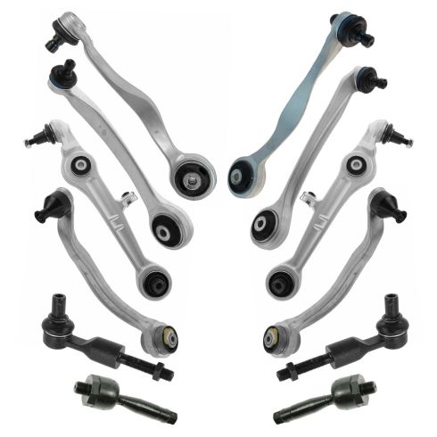
Kit Includes: (2) Front Outer Tie Rods (2) Front Inner Tie Rods (2) Front Lower Rearward Control Arms with Ball Joints (2) Front Lower Forward Control Arms with Ball Joints (2) Front Upper Rearward Control Arms with Ball Joints (2) Front Upper Forward Control Arms with Ball Joints
Quantity: 12 Piece
Specification
Location
Front
TRQ suspension kits are manufactured using premium raw materials and coatings for extended service life. Each TRQ suspension component is designed to be a direct, maintenance-free replacement to the stock unit. To extend the life of your steering and suspension components, TRQ recommends replacing components in pairs, sets, or kits. All products are fit and road-tested in our Massachusetts R&D facility to ensure we deliver on our promise of Trusted Reliable Quality.
Product Features
Application Specific Design: No modifications necessary
Anti-Corrosion Coated: Enhanced surface life
Pre-greased: No additional maintenance required
Kitted for Restored Performance: Improved road-feel and handling
Install Tip: When replacing steering components, have a professional alignment performed afterwards. This ensures proper tracking and even tire wear.
Our steering and suspension components are pre-greased and sealed for long life and do not require the extra maintenance typically required by greaseable versions.
Item Condition:New
Attention California Customers:
WARNING: This product can expose you to chemicals including Lead and Lead Compounds, which are known to the State of California to cause cancer, and birth defects or other reproductive harm. For more information, go to www.P65Warnings.ca.gov.
Lifetime Warranty
This item is backed by our limited lifetime warranty. In the event that this item should fail due to manufacturing defects during intended use, we will replace the part free of charge. This warranty covers the cost of the part only.
FREE Shipping is standard on orders shipped to the lower 48 States (Contiguous United States). Standard shipping charges apply to Hawaii and Alaska.
Shipping is not available to a P.O. Box, APO/FPO/DPO addresses, US Territories, or Canada for this item.
Expedited is available on checkout to the United States, excluding Alaska, Hawaii.
Final shipping costs are available at checkout.
How to Replace Front Upper Control Arms 2002-09 Audi A4
Created on:
Tools used
Socket Extensions
Torque Wrench
16mm Wrench
Hammer
Tie Rod Fork
Ball Joint Press
Rust Penetrant
Channel-Lock Pliers
18mm Wrench
16mm Socket
Jack Stands
18mm Socket
Pick
Audi Wheel Cap Removal Tool
Phillips Head Screwdriver
Chisel
Ratchet
Floor Jack
1. Removing the Wheel
Remove the center cap with a cap removal tool or pick
Loosen the 17mm lug nuts with the vehicle on the ground
Raise the vehicle with a floor jack
Secure the vehicle on jack stands
Remove the lug nuts
Pull off the wheel
2. Simulating the Suspension
Push up on the suspension with a floor jack until the suspension stops compressing
Measure the top of the strut mount and mark from the front of the tap to where it lines up at the bottom (3 1/4 inches)
Lower the floor jack to release the weight from the suspension
3. Removing the Strut Assembly
Remove the pinch bolt with a 16mm wrench and 16mm socket and ratchet
If the bolt won't remove, use a chisel and hammer
Slide a pickle fork under the joint
Hammer the pick fork in until it separates from the spindle
Remove the Phillips head screw from the coolant tank
Slide the tank out of its retainers
Remove the 16mm bolt below the expansion tank
Remove the rain tray
Pull off the rubber boot before the fuse box
Remove the 16mm bolt
Remove the 16mm bolt by the fuse panel
Remove the bolt from the bottom of the strut with a an 18mm socket and 18mm wrench
Remove the strut from the lower control arm
4. Removing the Upper Control Arms
Remove the 16mm bolts holding in the upper control arms
Remove the upper control arms
5. Installing the Upper Control Arms
Insert the upper control arm into place
Remember to transfer the mark you used to measure the angle of the control arms
Set the angle
Tighten the 16mm bolts
Torque the control arm bolts to 37 foot-pounds and add 90 degrees
Repeat the process for the other side
Remove the protective caps from the new boots
6. Reinstalling the Strut Assembly
Insert the strut assembly into place
Tighten the top strut bolts
Torque the strut bolts to 55 foot-pounds
If the strut rotates, twist it to it's in place
Tighten the lower strut bolt with an 18mm socket and wrench
Reinstall the forward control arm into the spindle
Press the control arm into the spindle with pliers
Insert the pinch bolt in halfway
Reinstall the nut on the back of the pinch bolt with a 15mm socket and wrench
Torque the pinch bolt to 30 foot-pounds
Torque the lower strut bolt to 66 foot-pounds
7. Reattaching the Wheel
Slide the wheel into place
Start the lug nuts by hand
Tighten the lug nuts preliminarily
Lower the vehicle to the ground
Tighten the lug nuts to 90 foot-pounds in a crossing or star pattern
Reattach the center cap
Brought to you by 1AAuto.com, your source for quality replacement parts and the best service on the Internet.
Hi, I'm Mike from 1A Auto. I hope this how-to video helps you out, and next time you need parts for your vehicle, think of 1AAuto.com. Thanks.
In this video, we're going to show you upper control arm replacement on this 2007 Audio A4. Pretty much the same for 2000 to 2008. You'll need a center cap removal tool or 90 degree pick, 16 to 18 millimeter sockets with ratchets and extensions, 16 to 18 millimeter wrenches, penetrating oil, chisel, hammer, ball joint or tire rod fork, Phillip's screwdriver, torque wrench, large pliers and jack and jack stand.
To remove the wheel, you'll have to remove this lug cover. You can use the tool supplied with your spare tire kit. Often these are missing and are available on 1AAuto.com or you can use a hooked pick.
Remove the five 17 millimeter wheel bolts. I'm going to use the screw jack to push up on the suspension and simulate the weight of the vehicle on the tires. You can do the same thing with a floor jack at home. Bring it up until the suspension stops compressing. Hook a measuring tape to the top of your strut mount. Mark where you put the front of the tape on the strut mount and where it lines up at the bottom.
Our measurement here is 3 1/2 inches. Since the arms can't be torqued inside of the vehicle we will use a recreation of this measurement to set the angle of the control arm with the weight on before you torque on the bench. This arm will be aligned with our tape at both marks to 3 1/2 inches. We'll make our other arm parallel before torqueing on the bench.
Lower your screw jack or floor jack to release the weight from the suspension. Remove the pinch bolt at the top of the spindle. Often these are frozen in and will require heat power tools and just generally a lot of working back and forth to remove, but we're going to try starting ours by hand. You'll need a 16 millimeter wrench and a 16 millimeter socket and ratchet. Often even once the nut's been removed these pinch bolts tend to get stuck in the spindle. The best thing you can do for this is spray penetrating oil just about anywhere you can get at the bolt.
If you have to get a little outward pressure while you try to turn the bolt out of the spindle, you can use part of a chisel behind the washer just to put some outward pressure on it while you try to turn it out. We're going to be using a very thin wrench to get behind the washer, pry out on the bolt while we turn. When all else fails, you may just have to use power tools.
As the gap behind the washer gets bigger, you can up-size wrenches or even double them up to fill the gap. The best way to remove the upper control arms from the spindle is with a ball joint or a tire rod fork. Simply slide it under the joint, send it in with a hammer until it separates from the spindle. Remove the Phillips head screw on the top of the coolant expansion tank. Slide the tank out of its retainers. Just lay it off to the side. Be careful not to spill.
Remove the 16 millimeter bolt below the expansion tank. Our vehicle is missing the rain tray. If yours isn't, you'll have to remove it to access this rubber plug just before the fuse box. Remove the 16 millimeter bolt underneath. Remove the last 16 millimeter bolt between the break booster just by the fuse panel.
Using an 18 millimeter socket and ratchet and an 18 millimeter wrench, remove the bolt from the bottom of the strut through the lower control arm. Remove the bottom of the strut from the lower control arm and pry out to release the clip. With the strut assembly removed remove the 16 millimeter bolts holding in the upper control arms.
Reinstall your upper control arms. Remember to transfer the mark you used to measure the angle of the control arms from your old part to your new part so we can set the angle and torque the control arms appropriately. Torque the upper control arm bolts to 37 foot-pounds and then add 90 degrees.
Reinstall the other control arm the same way. Remove the protective caps on the new boots and you're ready to reinstall the assembly into the vehicle. Reinstall your strut assembly into the wheel well. Reinstall your top strut bolts. Torque the strut cap bolts to 55 foot-pounds. The strut may have rotated. All you have to do is use a small pry bar to twist it the way you want it. Once you're lined up send your bolt back through, tighten it back up with an 18 millimeter socket and ratchet and wrench.
Reinstall your forward control arm into the spindle. You may need a large pair of pliers to press the control arms into the spindle. Once it's in, install the pinch bolt halfway to keep it from falling out.
Reinstall the nut on the back of your pinch bolt. Tighten it down with a 16 millimeter socket ratchet and wrench. Torque the pinch bolt to 30 foot-pounds. Using your floor jack or screw jack to simulate the weight of the suspension on the vehicle torque your lower strut bolt to 66 foot-pounds.
Reinstall the wheel onto the hub. It helps if you send a lug bolt through and hold it with a 17 millimeter socket on the other side. Start the first bolt by hand to help keep the wheel in place. Torque the lug bolts to 90 foot-pounds in a cross pattern. The slots on the back of the lug cap are staggered. Be sure to align them before installing.
Reinstall the rubber cap and the rain tray if your vehicle has one. Reinstall the coolant reservoir into the slots on the fire wall. Reinstall the Phillip's head screw to secure it.
Thanks for tuning in. We hope this video helped you out. Next time you need parts for your car, please visit 1AAuto.com. Also check out our other helpful how-to and diagnosis videos.
PSA59208
In Stock
Product Reviews
Loading reviews
2.00/ 5.01
1review
5 Stars
4 Stars
3 Stars
2 Stars
1 Star
0
0
0
1
0
Bad piece in kit.
Z
September 5, 2017
I ordered a 10 piece Control arm kit for my suspension... One of the pieces had a ball joint that was bad and was only able to torque it to about 40 foot pounds before the whole thing started spinning and cannot get it tight. Honestly I'm pretty worried about my safety driving now.
Customer Q&A
No questions have been asked about this item.
Customer service
877-844-3393
Monday - Friday 8:00am - 9:30pm ET Saturday - Sunday 8:00am - 4:30pm ET
Audi is a registered trademark of Audi AG. 1A Auto is not affiliated with or sponsored by Audi or Audi AG.See all trademarks.
Enter Vehicle Year Make Model
Specify your vehicle's year, make and model to guarantee fit.
Year
Make
Model
Options
Drivetrain
This part doesn’t fit a . Select from parts that fit.