Replaces


Part Details
Specifications
Product Features
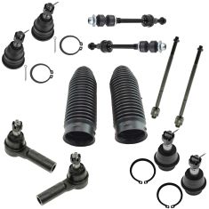
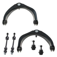
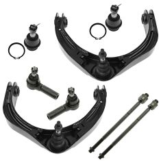
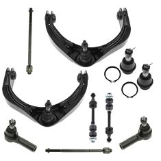
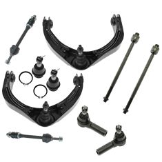
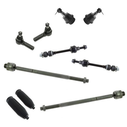
TRQ suspension kits are manufactured using premium raw materials and coatings for extended service life. Each TRQ suspension component is designed to be a direct, maintenance-free replacement to the stock unit. To extend the life of your steering and suspension components, TRQ recommends replacing components in pairs, sets, or kits. All products are fit and road-tested in our Massachusetts R&D facility to ensure we deliver on our promise of Trusted Reliable Quality.
Install Tip: When replacing steering components, have a professional alignment performed afterwards. This ensures proper tracking and even tire wear.
Our steering and suspension components are pre-greased and sealed for long life and do not require the extra maintenance typically required by greaseable versions.
Attention California Customers:
 WARNING: This product can expose you to chemicals including Lead and Lead Compounds, which are known to the State of California to cause cancer, and birth defects or other reproductive harm. For more information, go to www.P65Warnings.ca.gov.
Lifetime Warranty
This item is backed by our limited lifetime warranty. In the event that this item should fail due to manufacturing defects during intended use, we will replace the part free of charge. This warranty covers the cost of the part only.
FREE Shipping is standard on orders shipped to the lower 48 States (Contiguous United States). Standard shipping charges apply to Hawaii and Alaska.
Shipping is not available to a P.O. Box, APO/FPO/DPO addresses, US Territories, or Canada for this item.
Expedited is available on checkout to the United States, excluding Alaska, Hawaii.
Final shipping costs are available at checkout.
Created on:
Tools used
Brought to you by 1AAuto.com, your source for quality replacement parts and the best service on the Internet.
Hi, I'm Mike from 1A Auto. I hope this how-to video helps you out, and next time you need parts for your vehicle, think of 1AAuto.com. Thanks.
In this video, we're going to show you how to replace the outer tie rod end on this 2008 Dodge Ram 1500. This is for a non-mega cab truck. We're doing the passenger side, but this information will be exactly the same on the driver's side.
Here are the item's you'll need for this repair: 22-27mm socket, 1/2 breaker bar, ratchet, socket extensions, breaker bar, 24mm wrench, torque wrench, jack and jack stands.
With the vehicle on the ground, using a 22mm socket and a breaker bar, break the lug nuts for your wheel loose. These chrome lug nuts tend to be swollen, so make sure your socket's on there good. Once your lug nuts are loose, raise and support the vehicle with a jack and jack stands.
This wheel and tire assembly, being a big off road tire and 20 inch wheel, it's going to be real heavy, so we're only going to bring it up a little bit when we take it off. Remove the wheel and tie from the hub.
The tie rod end is located at the end of the inner tie rod and bolts into this spindle. We're going to use a 24mm wrench to break the lock nut loose just a little. Use a 22mm deep socket and a ratchet to remove the nut on the bottom. Going to hit the side of the spindle to release the tie rod. After a few good hits, should be able to knock it out of the spindle. Remove the tie rod end from the spindle and unthread it from the inner tie rod.
Here we have our old part that we removed from our 2008 Dodge Ram. Here we have our new tie rod end from 1AAuto, part number 1ASTE00402. As you can see, they're very similar, some minor differences in the aesthetics, but the actual stud to go into the spindle is correct. They have the same size threads. They're the same length. Our new part comes with a castle nut and a cotter pin, which is more secure than the factory flange nut.
Some symptoms of a bad tie rod end can be play in the steering wheel. Could also cause an unusual tire wear pattern or you can feel that you may need to use a lot more force than you're used to when trying to turn the wheel. If your vehicle is suffering from any of these symptoms and you've deduced that it's the tie rod end, this new part from 1AAuto is going to go in, direct-fit, just like your original equipment, and fix you up right.
Thread the new tie rod end onto the inner tie rod. We'll reinstall it into the spindle. Start the new castle nut on, tighten it down with a 27mm socket and ratchet. Torque to 45 foot-pounds, then add an additional 90 degrees. Install the cotter pin, then the long tab down under the bottom of the bolt. Cut the short end off flush.
Using a 24mm wrench, tighten the lock nut on the inner tie rod back against your outer tie rod end. Start your lug nuts by hand. Tighten the lugs as far as you can. Remember to bring the wheel down evenly and always tighten in a cross pattern. Once the lugs are as tight as you can get them with the tire in the air, put partial weight of the vehicle on the ground by lowering it off your jack stands. Torque your lug nuts to 135 foot-pounds in a cross pattern. Bring the vehicle for a professional alignment.
Thanks for tuning in. We hope this video helped you out. Next time you need parts for your car, please visit 1AAuto.com. Also check out our other helpful how-to and diagnosis videos.
Tools used
Brought to you by 1AAuto.com, your source for quality replacement parts and the best service on the Internet.
Hi, I'm Mike from 1A Auto. I hope this how-to video helps you out, and next time you need parts for your vehicle, think of 1AAuto.com. Thanks.
In this video, we're going to show you how to replace the lower ball joints in this Dodge Ram. This one is a 2008, but the procedure is pretty much the same for 2006 to 2008 1500 Dodge Rams. We do this on the passenger side, but the driver's side is the same procedure.
You'll need new ball joints from 1AAuto.com, 8 to 35 millimeter sockets with a ratchet and extensions, a breaker bar, hooked picked, bungee cords or mechanics wire, pry bar, hammer, flat blade screwdriver, needle nose pliers, snap ring pliers, ball joint press, torque wrench, and jack and jack stands.
With the vehicle on the ground, using the 22 millimeter socket and breaker bar, break the lug nuts for your wheel loose. These chrome lug nuts tend to be swollen, so make sure your socket's on there good. Using the small pick, remove the center cap from the wheel. Using a 35 millimeter socket and a breaker bar crack the axle nut loose. Raise and support your vehicle. Finish removing the lug nuts. Remove the wheel and tire from the hub.
Remove the two 21 millimeter bolts securing the caliper bracket to the spindle. Be sure to crack both of these loose before removing them. If they are removed fully one at a time, the caliper can twist and cause the flex hose on the brake line to tear. Be sure to support the assembly while you remove the last bolt. Remove the entire caliper and carrier assembly. Using a bungee cord secure it out of the way by hanging it off of the frame. Remove the rotor from the hub.
Brace the hub with a pry bar and finish removing your axle nut. Using a hammer, tap the end of the axle to push it out of the hub. Remove the nut for the tire rod. Take a 21 millimeter socket and ratchet. You want to leave the nut on a few threads so that it's flush with the bottom of the stud. Carefully tap up with a hammer. Remove the nut. Remove the tie rod from the control arm. Remove the 22 millimeter nut connecting the upper ball joint to the spindle.
Tap the front of the knuckle right where the ball joint comes through with a hammer to release it, careful not to hit it too hard because this is aluminum and it could crack. Once it's loosened up, you may have to hit the bottom of the control arm to release the joint from the knuckle. Using a flat blade screwdriver, release the tab on the connector for the ABS sensor. Push down and release the connector. Release it from the clamps under the control arm.
Pull down on the spindle or push up on the upper control arm to separate them and remove the axle shaft from the wheel bearing.
With a pair of needle nose pliers, straighten out the legs on the cotter pin. You want to get them as tight as you can, and as free of kinks as possible. This may mean pinching them together, and working them back and forth a little. Keep them together. Stick one of the legs from your pliers through the eyelet of the cotter pin. Clamp down, and twist it out. Regardless of whether or not the cotter pin comes out in one piece, you will want to replace these after they've been removed.
Using a 22 millimeter socket and breaker bar, remove the nut on the lower ball joint. Ensure that your axle nut is partially installed so the hub—once released from the ball joint—does not fall. Put some weight onto the top of the spindle, either by pulling down with your hand or a pry bar, and hit the bottom of the spindle here with a hammer to release the ball joint from the spindle. Once the ball joint is separated from the spindle, remove your axle nut the rest of the way.
Release the axle from the hub and the spindle from the ball joint. Using a bungee cord, zip ties, or mechanics wire, secure your CV axle up and out of the way of your lower ball joint. Using a pair of normally closed snap ring pliers, release the snap ring on the top of the ball joint. Place the receiving tube onto the bottom of the lower ball joint. Set it onto your press. Install a cup onto the top of the press to protect the grease fitting and to keep the press centered.
Using a 22 millimeter socket and breaker bar, tighten down on the press until the ball joint is released from the control arm. We're going to use an 8 millimeter socket to remove the grease fitting in order to get the added clearance to finish pressing the joint out.
Now you'll put your tube back onto the bottom of the ball joint. Reinstall your press, and without a cup on the top, put the threaded end of the press directly onto the top center of the ball joint. Press it the rest of the way out. When the joint is close to coming out, hold the press if it's safe to do so. Remove the assembly from the control arm.
Here we have our old ball joint, which we removed from our truck, and our new ball joint from 1A Auto. As you can see, there are some minor aesthetic differences, but the taper and the diameter of the joint are exactly the same. Same spline, they have a nice new boot, this one on our vehicle had actually collapsed in some, which obviously isn't going to hold grease very well. It's all dried out and rusted inside—I can barely get this thing to move.
Our new ball joint comes with a new snap ring that will sit on top of the control arm, to keep from the vehicle moving up and down and from working the ball joint out of its seat; A 90 degree zerk fitting, which is actually going to be a lot easier to access inside the vehicle; A new castle nut; And a new cotter pin to secure it and keep it from turning out. When it comes time to remove this ball joint in the future, you'll see that we have a slot in there, which allows you to keep the ball joint in place with a flat blade screwdriver, while undoing this castle nut, making it easier to remove a stubborn old ball joint, whereas this one has no provision to keep it from spinning.
Install the ball joint into an installation cup that fits the rim of the joint as best you can. Install the joint into the spindle with the cup on top, which will allow the joint to come through until it bottoms out. Make sure it's in there nice and straight. Using a 22 millimeter socket and ratchet, tighten it down until the joint seats fully into the lower control arm. Once you can see that the ball joint is seated fully, all the way around the control arm, remove your ball joint press.
Use your snap ring pliers to spread the new snap ring. Install it into the groove of the ball joint. Be sure that it's fully seated in there. Install your zerk/grease fitting. Using a 10 millimeter socket, tighten down your grease/zerk fitting. Be sure to face it in a direction that won't be interfered with by the spindle, such as backwards or forwards, as long as you can do so without stripping it.
Install the ball joint as well as the CV axle into the spindle, making sure that both line up properly. Start the washer and castle nut onto the threads of the ball joint. Line up and install the spines of your axle into the hub. Start your axle nut on as far as it'll go. Lift up on the upper control arm, slide the upper ball joint into the spindle. Pull down until you're able to get the nut started onto the threads. Tighten it down with a 22 millimeter socket and ratchet. Torque the upper ball joint to 40 foot-pounds. Add an additional 90 degrees.
Reinstall the tie rod into the spindle. Start the nut. Tighten it with a 21 millimeter socket and ratchet. Torque the tie rod to 45 foot-pounds. Reinstall the harness into the keepers and the bottom of the control arm. Reinstall the connector.
Push down on the safety tab. Reinstall the rotor onto the hub. Make sure that you don't twist the line on your brake hose. Reinstall the caliper carrier assembly onto the rotor. Start the bolts on the back side. Tighten the bolts down with a 21 millimeter socket and ratchet. Torque the caliper bolts to 130 foot-pounds.
Reinstall your wheel and tire onto the vehicle. Start the lug nuts with a 22 millimeter socket. Get all the lug nuts as tight as you can in the air and lower the vehicle. After tightening your axle nut torque it to 185 foot-pounds. Pop the center cap back into place. Torque your lug nuts to 135 foot-pounds in a cross pattern.
Thanks for tuning in. We hope this video helped you out. Next time you need parts for your car, please visit 1AAuto.com. Also check out our other helpful how-to and diagnosis videos.
Tools used
Brought to you by 1AAuto.com, your source for quality replacement parts and the best service on the Internet.
Hi, I'm Mike from 1A Auto. I hope this how-to video helps you out, and next time you need parts for your vehicle, think of 1AAuto.com. Thanks.
In this video we're going to show you how to replace the sway bar end links on this 2008 Dodge Ram. Typically, you want to replace them in pairs. These are the tools that you're going to need: rust penetrant, 15mm, 16mm, 17mm, 18mm sockets, ratchet, socket extension, locking pliers, torque wrench, jack and jack stands
Raise and support your vehicle. You can do it with jack stands, but in this case we have a lift so we're going to use the lift. In the front end of the truck you can see that your sway bar end link is right here. We're going to start by shooting the threads with some rust penetrant so that it makes our whole job a whole lot easier.
To remove the sway bar end link, you're actually going to have to rotate the sway bar up. To do that, you have to disconnect the opposite side sway bar end link. If you're going to just be replacing one of the sway bar end links, then you just need to disconnect the bottom of the other side, but if you're going to be replacing both like us, and we recommend replacing both at the same time, you're going to want to lubricate the top and the bottom with the penetrating oil.
You'll see that the sway bar end link has a 15mm hex on the bottom side of it so that you can hold it with a wrench. Then on the top you're going to need a 17mm deep socket and ratchet. The bottom end of the sway bar end link has an 18mm spot for a wrench on it. You can wedge it in between the wheel. The bottom side is an 18mm 6-point. Now you can take the nut right off the bottom. We're going to be replacing both of the sway bar end links, but if you're just doing one, you need to disconnect the opposite side, the bottom of it. The 18mm wrench that we were hoping to use didn't fit in this scenario, so we went right to the locking pliers.
With an 18mm socket on the bottom, you should be able to loosen it right up. Then you can pop the nut right off the bottom. Now we need to raise up the sway bar so that we can pull the sway bar end links out. Unfortunately, we just put brand new bushings in here, so the sway bar is really tight, and it's tough to push up. We're going to start by loosening up the sway bar bushing brackets. You don't have to take all the bolts out. We just need to loosen them up so that the sway bar will move a little freer.
Now we're going to push the sway bar up on this side so that we can come over here and remove the sway bar end link from the sway bar. We're going to be replacing both of the sway bar end links, so the next thing that we do is rotate the sway bar like this. You haven't easier access to this upper nut on the sway bar end link. You can put a 15mm here, 17mm socket on the top, and loosen it up.
This right here is a 1ASSL00405. This is also an aftermarket piece; it's actually been replaced before on the truck. You can see that they're obviously very similar. Ours has the new bushings and washers, and nuts, along with the grease fitting included. The only difference between these two that I can come up with is these points right here, where you put the wrench on to remove them. It's just 18mm versus 19mm. It's going to fit just like the original one does and hopefully solve your problem.
Get your 1A Auto sway bar end link, and take the nut and the washer and the rubber bumper off the top, leaving one rubber bumper and the washer on there. Slide it through your sway bar. Then put the nut on, but leave it really use so that we can actually slide it down into the control arm later. We're going to repeat this step on the opposite side. We're now going to spin the sway bar up, and set the sway bar end links down through the control arms. Then we'll loosely install the nuts on the bottom of the sway bar end links.
We're going to start by tightening up the top of the sway bar end link with a 15mm wrench right in here and a 16mm socket and ratchet on the top. Just snug it up. Then we'll move to the bottom. We'll take a 19mm wrench, slide it right over here, and an 18mm socket and ratchet for the bottom. Once it's tight, you'll want to repeat these steps on the opposite side.
Next, we're going to tighten up all of the sway bar bushings bolts that we had loosened earlier in the job. These we should set to 45 foot-pounds. With the sway bar bushings torqued and the sway bar end links replaced, now you can lower the truck back down to the ground and you'll be all set for the road ahead.
Thanks for tuning in. We hope this video helped you out. Next time you need parts for your car, please visit 1AAuto.com. Also check out our other helpful how-to and diagnosis videos.

PSA63416