Replaces
Part Details
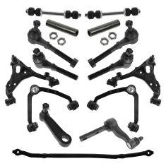
TRQ suspension kits are manufactured using premium raw materials and coatings for extended service life. Each TRQ suspension component is designed to be a direct, maintenance-free replacement to the stock unit. To extend the life of your steering and suspension components, TRQ recommends replacing components in pairs, sets, or kits. All products are fit and road-tested in our Massachusetts R&D facility to ensure we deliver on our promise of Trusted Reliable Quality.
Product Features
Install Tip: When replacing steering components, have a professional alignment performed afterwards. This ensures proper tracking and even tire wear.
Our steering and suspension components are pre-greased and sealed for long life and do not require the extra maintenance typically required by greaseable versions.
Item Condition:
New
Attention California Customers:
 WARNING: This product can expose you to chemicals including Lead and Lead Compounds, which are known to the State of California to cause cancer, and birth defects or other reproductive harm. For more information, go to www.P65Warnings.ca.gov.
Lifetime Warranty
This item is backed by our limited lifetime warranty. In the event that this item should fail due to manufacturing defects during intended use, we will replace the part free of charge. This warranty covers the cost of the part only.
FREE Shipping is standard on orders shipped to the lower 48 States (Contiguous United States). Standard shipping charges apply to Hawaii and Alaska.
Shipping is not available to a P.O. Box, APO/FPO/DPO addresses, US Territories, or Canada for this item.
Expedited is available on checkout to the United States, excluding Alaska, Hawaii.
Final shipping costs are available at checkout.


Created on:
Tools used
To remove the idler arm from the steering, raise and support your vehicle. Go underneath here to the castle nut and start by removing the cotter pin with some side-cutting pliers. The goal is to not cut it, but just get a hold of them and bend it until it's kind of straight. Sometimes they break off. You can kind of grab the rounded end and try to pry against it like this. Just keep readjusting it. Just pry and there you go, pull it out.
Loosen the 21 millimeter castle nut. You can use a socket and a ratchet or a wrench. This one is pretty tight, so I've switched to a breaker bar. There it is. I will switch back to my ratchet now that it's broken free. Once this is loose, take it off by hand.
This one's actually really loose and it came right now. If this was stuck on the taper, because this is tapered and it jams into the steering control rod, you would take a idler arm puller tool, place it in here and you would turn this with your wrench and it would separate the idler arm from the steering control rod, but we got lucky on this one and it slid right off.
Remove the two 21 millimeter bolts that are holding the idler arm to the frame. Use my 21 millimeter box wrench, break these free. Now that these are broken free with my 21 millimeter box wrench, I'm going to use a 21 millimeter socket, ratchet, and extension. Just make it go a little quicker. Got one. Now we're going to hold the idler arm with one hand, take out the last bolt. And we can pull it from the frame.
Here's our old idler arm from our vehicle. Here's our new idler arm from 1AAuto.com. The dimensions between the bolt holes are the same. Their design is a little bit different but the dimensions from here to here match up.
Before you install it, you want to remove the brand new castle nut it comes with, take off the plastic cover that protects the boot during shipping. It also comes with a new cotter pin, a new grease fitting to go down here, and a new grease fitting to go down the side of this joint here. It should make the steering feel a lot tighter on your vehicle.
Install our new grease fittings, just by hand. Take a small 9/32 inch wrench on this one. A couple turns, just so it's tight, and stop. There’s one on this side. Then reinstall the idler arm to the frame. Start with my top bolt, then the lower bolt. Install that. Use my 21 millimeter ratchet and extension, finish installing it. Stop this as it gets tight, because I will come back and torque these afterwards.
Reinstall our steering linkage. Push it up there with a new castle nut. Use a 21 millimeter socket and ratchet. The torque spec on this is 56 to 84 foot-pounds, so I'm going to torque it 70. This way if you need to go more, you can, but by torquing it you should be able to seat it onto the taper. So if you turn it and the castle nut doesn't line up with the hole for the cotter pin, by giving yourself some more room on the torque number we can actually tighten this a little bit more. Just going to go maybe a quarter of a turn to get the hole to line up. Finds it nice. Grab it, bend it down and then the other one the other way. The torque for these two bolts is 126 to 169. We're going to do 140 foot-pounds. Get our torque wrench in here.
I'm going to grease these fittings. So just grease these until you start to see a bit of grease come out right here. You can actually see the boot fill up with grease. That looks nice and full, a little bit of grease coming out and then you can stop. Wipe up the excess grease, and your job is complete.
Thanks for watching. Visit us at 1AAuto.com for quality auto parts, fast and free shipping, and the best customer service in the industry.
Tools used
Brought to you by 1AAuto.com, your source for quality replacement parts and the best service on the internet.
In this video I'm going to show you how to replace the stabilize links on this 97 expedition, same as many Ford and Lincoln trucks and SUVs. When these go bad, sometimes they break out right and just kind of fall out and then your truck is going to sway back and forth more. Also you may here a clunking when you go over bumps and that clunking actually goes away when you're going over bumps but you're turning, because it's putting some pressure on the Lincoln and not making noise.
Tools you'll need, I put jack and jack stands on here but you can actually accomplish this with the vehicle on the ground. Obviously it's a lot easier to film it with jack and jack stands but you will need 9/16 and 14mm sockets. The 19mm socket will be if you're taking the lug nuts off. Ratchet and extensions. You'll need a hummer and a punch, vise-grip or locking pliers and penetrating oil. Actually those last four things are only if yours is rusted on there like ours was.
Okay, to film it, it's a lot easier to take the wheel off. This is a repair you can do just by turning if you want to replace the right hand one you can turn your wheels all the way to the right and you can probably get in there well enough, remove the stabilizer link without jacking up the vehicle or taking the wheel off. I'm going to loosen the lug nuts here then raise and secure the vehicle and remove the tire.
Next I'm going to remove the stabilizer links. I'm going to spray the top of it with some penetrating oil and let it sit for a while. Okay this stabilizer links are sometimes difficult to get apart. You can use hand tools, they will come apart. I just chose to use a impact wrench just to make it easier. I have a 9/16 socket on the bottom and a 14mm socket on top.
Okay, use a hummer and pound down that bolt then use punch see if you can get it to go down through the sleeve, I end up actually having to use vise-grips and the wrench. Okay what I'm going to do here, I'm going to set up vise-grips on to this shaft, more tighter here. Here I'm going to install the sway bar link. I've already put a new link on the other side and just started the nut on it. The bushing always go towards the middle. We got bushing on the bottom going up to the control arm, bushing above that. My shaft goes on there and then the washer and the bushing. Okay push them down and in, and make sure that bushing is centered in there. Stabilizer bar. Now bushing and washer, and then my bolt or nut.
Okay, now you want to use the jack put pressure on the suspension and then tighten up the stabilizer to 15, to 17 foot pounds. You can put your tire back on and start each lug nut one by one make sure you don't cross-thread them. Tighten them down preliminarily. Put the lug nuts to 100 foot pounds using a star pattern.
We hope this helps you out. Brought to you by www.1AAuto.com your source for quality replacement parts and the best service on the internet. Please feel free to call us toll free 888-844-3393. We're the company that's here for you on the internet and in person.
Tools used
Brought to you by 1AAuto.com, your source for quality replacement parts and the best service on the internet. In this video, we're going to show you how to remove and replace the upper control arm on this 1997 Expedition. At 1A Auto, we sell a nice replacement upper control arm. This takes care of if you have worn out bushings as well as a worn out upper balljoint. Replacing the whole assembly will take care of both those issues. We're doing this on this Expedition, but it's also the same for a lot of different Ford and Lincoln SUVs and pickup trucks.
Tools you'll need are 19 and 21 mm sockets and that could vary depending on what vehicle you're working on, a ratchet, breaker bar, and a pipe for leverage. Some of those bolts can be a little stubborn so having some extra leverage is always good, pliers, penetrating oil, a marker, a balljoint removal tool, a hammer, as well as jack and jackstands.
We're going to start out by removing your wheel. If you don't have impact tools, start with your wheel on the ground. Loosen the lug nuts then raise and support the vehicle, then take the lug nuts off and the wheel off. Once you have the tire off, you're going to want to roll a jack underneath the lower control arm and lift up and support the suspension. Now there's basically three bolts. You've got the balljoint bolt here that you're going to remove. You have to take the cotter pin out first. Then you have two bolts up here that hold it to the frame, and one there and then obviously one right here. The bolts and washers that hold the control arm to the frame are actually what you use to align and set caster and camber. What I'm going to do is I'm going to use a marker and just make a vertical line on them so I have a good reference point to put them back together which gives you a pretty decent preliminary alignment. You will want to have your alignment checked and possibly adjusted after this repair.
What I'm going to do, I'm going to take a black marker and we'll make a line just straight up and that would I know that, that one's in there like that and then same thing over here. Make a line straight up so I know how they came out. Here, I'm using a pair of pliers and just grab in the ends of the cotter pin that have been pushed through and bent and you basically just break them off, that's usually the easiest way then you can pull it out from the other side. There's the cotter pin. I am going to get my screwdriver in here and pry that right out. I'm going to spray that with penetrating oil, also spray my other ones up top here.
Now, I'm going to take a 21mm socket and put it on that bolt. Now, I'm using a hammer just to make sure it's all in there all the way. You're going to want at least a breaker bar and get it on here. Have to reposition my socket here so that I can make sure. I'm actually going to put an extra piece of pipe on my breaker bar. It gives me even more leverage. Get it loose. Now, I could switch to the ratchet and remove it all the way. I'm just going to keep the bolt on there a little bit. I'm going to turn my attention towards these bolts here. Same thing, get our socket on there.
Breaker bar, they seemed to be coming off all right. I loosen up that one a couple of turns then turn my attention towards the rear one. Use a hammer to try and get the socket on there. The bolt or the nut is a little crusty, so I just get it that on there and then it comes part as well. Once we get that bolt or the nut to the end there like that, our hammer, make sure we can get that bolt out. Here we're just making sure that we can get the bolts loose. You don't want to take them out yet, but you do just want to make sure, give him a couple of taps and turn them with a wrench and make sure they're free.
I was pleasantly surprised even though this truck is pretty crusty and rusty, they did come free pretty easily. Now, you're going to want to remove the nut from the upper balljoint and then use a balljoint puller tool to separate the arm, the control arm and the steering knuckle. You can see here I removed that plastic around the upper balljoint then put my balljoint separator tool on and get it in position. I'm going to use this, the 19 mm and you basically just tighten it up until it pops. You see your steering knuckle comes out of the way. Now, I just remove the nuts and washers from the ends of those bolts that hold the frame.
Pull the bolts out. I just kind of put everything right on the frame next to it so I keep the same hardware with the same sides. Take my old control arm out. Use a wire brush and or a screwdriver, just clean off some of the scale on the inside of the frame there then put your new control arm up in place and you just want to start the bolts in. For right now, pay attention to where the marks are that you made on the washers on the bolt heads. Just work them right into place. All right, I've got the bolts in. I'm going to now just put this down and in.
Just start my bolt on. Now, I'm just going to kind of preliminarily tighten these up. I'm going to put my breaker bar on here. I'm just kind of pulling that so that my mark up there is straight up and down the way I marked it. All right, washer on the back, start my bolt on. Once I get the nut on there, I'll use my ratchet and socket and just tighten up that nut snug, you don't want to have it tight, just want to start getting seated and then repeat the same thing for the other frame bolt. I'm going to torque this balljoint nut to 67 foot pounds. Now, insert our new cotter pin and pliers to bend it, pull it through and bend it.
I'm just going to put little grease fitting on with an 8mm wrench or a pair of pliers, and then make sure we grease that upper balljoint. Basically just to install grease there's a small slot on the boot where the grease will start coming up once it's full. Now, we're going to raise the vehicle so that all the weight is on the suspension. I know the space between here, all my weight is on my suspension. I'm going to need my breaker bar. I'm looking at the mark I made to make sure it's still straight up and down. Put that on there to hold that and now I'm going to torque these nuts to 100 foot pounds.
We'll speed things up here as we repeat that for the other bolt and nut assembly. You can put your tire back on and start each lug nut one by one, make sure you don't cross-thread them and tighten them down preliminarily. Torque the lug nuts to 100 foot pounds using a star pattern. Then put your center cap back on and you should be all set. We hope this helps you out.
Brought to you by www.1AAuto.com, your source for quality replacement parts and the best service on the internet. Please feel free to call us toll free, 888-844-3393. We're the company that's here for you on the internet and in person.
Tools used
Hi, I'm Mike from 1A Auto. We've been selling auto parts for over 30 years. We're dedicated to delivering quality auto parts, expert customer service, fast and free shipping, all backed by our 100% satisfaction guarantee. Visit us at 1AAuto.com, your trusted source for quality auto parts.
So in order to start this project you want to go ahead and loosen the wheel and the lug nuts here. We're going to use a breaker bar with a 19 millimeter socket. So next we're going to go ahead and raise and support your vehicle. You can use a jack and jack stands. In this case here we're using a lift to make it a little bit easier. Just go ahead and remove the lug nuts here just by using that socket because we've already loosened those. With the lug nuts removed we can now go ahead and remove the wheel and tire.
So this right here is your outer tie rod end. We have the nut here to anchor this on. This is the castle nut. Normally you would have a cotter pin through here, but this did not have it in there. So it must have rotted or fallen out. So we're going to go ahead and remove this nut off of the outer tie rod end, and we're going to use a 13/16” wrench for this here.
So in order to remove this outer tie rod end, this actually fits into a tapered hole. What we can usually do in our driveway at home is, if you use a hammer and you strike the front here, it normally causes this to pop out. So now that we have this out, you can see that this is a tapered base, and this fits tightly into the front of the steering knuckle. So when you tighten up the castle nut, it sucks it down inside and keeps it nice and tight.
We're going to go ahead and replace the adjuster sleeve right here. We want to start by removing your outer tie rod end. Ideally, you want to count the amount of threads that this comes out on, so you have full rotation of this ball joint on your tie rod end.
Okay. We're going to use a 24 millimeter and we want to go ahead and basically unthread this off of the inner tie rod end. There we go. Now, because we're just replacing the adjuster sleeve, you can leave this jam nut right here, and when you take the new adjuster sleeve, just thread it right on up to that jam nut. There we go.
This here is the old part. This here is the new part from 1A Auto. If you notice, on the old part, we have the spot right here that has a flat section so you could put your wrench on there. Our part also has that. On the installation it is important to know that each side is a different diameter. The larger is the inner tie rod end port, and the smaller one is for the outer tie rod, so you can only put it on one way. Obviously if you have the smaller port, it just won't fit.
We're just going to go ahead and thread this on. When this threads on, you're going to notice that the wrench side is closer to the tie rod on the outer tie rod, but this here was closer to the inner. It doesn't matter. It's going to work the same exact way, it's just to give you an anchoring point for your wrench. Okay, you want to just crank that right up by hand up to that jam nut.
Now that we have the adjuster sleeve installed, because we don't actually have to replace this outer tie rod end, we can go ahead and get this installed now. In this component, we did count 31 full rotations. That means for the ball joint section facing down, a full rotation, that is one. We counted 31 of those there. In case you were installing a new outer tie rod end, you would have that count. I believe that was a 31. We'll just tighten up that jam nut by hand a little bit.
Then you're ready for your installation. Install your castle nut. You would tighten this up. Line up the castle nut with the hole in the outer tie rod end there. Use your cotter pin, feed it through, and then you're going to want to bend that over using a pair of pliers. Your adjuster sleeve may come with jam nuts. If your factory equipment is just fine, there's no need to replace them. Okay, so we're going to go ahead and tighten up these jam nuts.
All right, I'm going to go ahead and reinstall the tire. I'm going to go ahead and reinstall the lug nuts here. You want to get a few threads caught on all of these here. These lug nuts are 19 millimeters. So we're just going to snug these, bottom it out. Bottom the wheel out to the rotor. We're going to lower the vehicle down onto its own weight, and then do a final torque. With the vehicle on the ground, we're going to do a final torque of the wheel which is between 83 and 112 foot pounds. We're going to do it in a star pattern. All right, just double check the first one. She's all set.
Thanks for watching. Visit us at 1AAuto.com for quality auto parts, fast and free shipping, and the best customer service in the industry.
Tools used
Hi, I'm Mike from 1A Auto. We've been selling auto parts for over 30 years. We're dedicated to delivering quality auto parts, expert customer service, fast and free shipping, all backed by our 100% satisfaction guarantee. Visit us at 1AAuto.com, your trusted source for quality auto parts.
So, when we're going to start this project, we're going to go ahead and loosen the lug nuts on the wheel. We're going to use a breaker bar with a 19 mm socket. Next, we're going to go ahead and raise and support your vehicle. You can use a jack and jack stands. In this case, here, we're using a lift to make it a little bit easier. We just go ahead and remove the lug nuts here, just by using that socket, because we already loosened those. With the lug nuts removed, we can now go ahead and remove the wheel and tire.
Right about here, we have your sway bar or anti-sway bar end link, here. Here's your sway bar. In most cases, here, you'll find these sway bar end links broken. What we're going to do is we're going to show you how to go ahead and remove this and do an installation for you. This component, here, can actually be removed and replaced with the tire still on the vehicle. We just happened to have the vehicle up in the air with the tire off so it just made it a little bit easier. This is something you can do with the tire still on there.
All right, so we're going to use a 14 mm on the head of the bolt down below, and we're going to use a 14 mm on the top. It may vary on your application. I'm going to go ahead and remove this nut here. Now, this does come off in stages. You have your main washer. You have your rubber of poly bushing. Then, obviously, you have the sway bar link here, or the sway bar itself, anti-sway bar. I'm going to try and just tap this down. This bolt will slide out through the bottom. What we don't want to lose is all these components in the middle here. We're going to show you what those do. Before we pull this out, we're going to go ahead and start pulling apart the internal pieces here.
Here is your complete anti-sway bar end link. You can actually see it just starts off with just a basic bolt. Then you have your metal collar here. You want to make sure that that slides on so that the dish part is facing upward. Then you're going to take your component here. Your bushing could be a poly or rubber bushing. Slide that down. Now, this is going to go up inside the control arm. What you want to do is sleeve the components together. What's going to happen next is your next bushing is going to go on, followed by your next dish. Now this is going to go the opposite way, so it's going to compress and squeeze against its matching component. This here is simply just a sleeve. It's not threaded. Slips right down. Your next component is that there. Slide this on, and once again we're going to sleeve the other component, which is your sway bar, your anti-sway bar. That'll slip on followed by that, and followed by the nut. That there is your complete unit. Our vehicle doesn't actually need replacement, but this is just your R & R process.
Here's the reinstallation. Going to slide this up through the bottom, and go ahead and slide your bushing down, followed by that spacer and that washer. We're going to now go ahead and put the sleeve on. It's going to be the next bushing. I'm sorry, it's actually your spacer, here, first, then the bushing. Now, you have the slide this up underneath like so. You want to push that up, push that bolt up through the middle. Now, you can see the base bolt is in.
You have your bushing, collar, sleeve, collar, bushing. The bushing and the collar right there. The last component is the nut. We're going to go ahead and get the threaded on. We're going to go ahead and tighten this up with a 14 mm. As you're tightening this here, you may be wondering, "How tight do I tighten this here?" Well, basically you want to get it so that the rubber bushing expands out to roughly the diameter of the metal washers there.
I'm going to go ahead and reinstall the tire. I'm going to go ahead and reinstall the lug nuts, here. You want to get a few threads caught on all of these, here. These lug nuts are a 19 mm. We're just going to snug these, bottom it out, bottom the wheel out to the rotor. We're going to lower the vehicle down onto its own weight, and then do a final torque. With the vehicle on the ground, we're going to do its final torque of the wheel, which is between 83 and 112 foot pounds. We're going to do it in a star pattern. I'll just double check the first one. She's all set.
Thanks for watching. Visit us at 1AAuto.com for quality auto parts, fast and free shipping, and the best customer service in the industry.